Part 2: Connect ESP32 to the network
1. Luos engine in ESP32
We will illsutrate this second part of the tutorial with a button example. The next steps are the following:
- Using a Luos service
- Running Luos engine and the button package on ESP32
- Getting ready to be plug-and-play on the Luos network
The file main.c in the src folder of the example project is as followed:
#include "luos_engine.h"
#include "button.h"

void app_main(void)
{
    Luos_Init();
    Button_Init();

    while (1)
    {
        Luos_Loop();
        Button_Loop();
    }
}
The Luos service used here is the button service from the example.
If you want to create a new service, you can learn how to do it in the par one of the tutorial Your first service.
To implement Luos on a node and be connected to a Luos network, you need the following file and functions:
- luos_engine.h
Luos_Init()Luos_Loop()
Through this network, called Robus, you can send and receive messages between services. Luos provides ESP Familly with a hardware abstraction layer (HAL) based on the ESP-IDF SDK so that it becomes plug-and-play with ESP32 on a Luos network.
This HAL provides a systick, a timestamp data API and a communication bus based on UART, TIMER and GPIO.
This ESP32 becomes a node on the Luos network and must be connected with other nodes by a physical layer: a wire or an RS485 bus. Read our documentation for more information on hardware.
2. ESP32 development board's pins
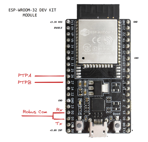
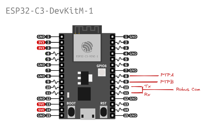
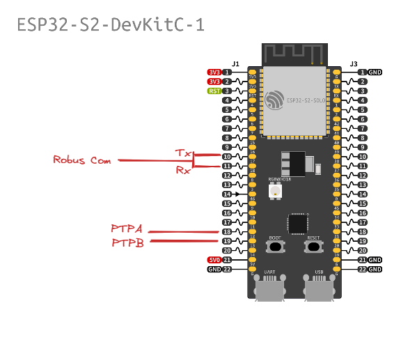
Depending on the development board you choose and on the MCU it contains, to do this tutorial you will have to adapt the connection. In Luos engine there is a default configuration for each ESP32 family, allowing it to be plug-and-play on the network.
You can find this default configuration in luos_engine/network/HAL/ESP32.
If you need to change the default pinout, you will need to add node_config.h to your project and reconfigure the pins defined by default in this file.
Pins needed for the Luos network:
- VCC and GND pins
- Rx and Tx pins (must be connected together in one-wire mode)
- At least two PTP pins
- Tx enable pin (only for RS485)
Default configuration:
- ESP32 series
- ESP32 C3
- ESP32 S2 and S3
| Pin Name | Property |
|---|---|
| PTPA_PIN | GPIO_NUM_26 |
| PTPB_PIN | GPIO_NUM_27 |
| TX_EN_PIN | GPIO_NUM_25 |
| COM_TX_PIN | GPIO_NUM_10 |
| COM_RX_PIN | GPIO_NUM_9 |
| Pin Name | Property |
|---|---|
| PTPA_PIN | GPIO_NUM_6 |
| PTPB_PIN | GPIO_NUM_7 |
| TX_EN_PIN | GPIO_NUM_9 |
| COM_TX_PIN | GPIO_NUM_4 |
| COM_RX_PIN | GPIO_NUM_5 |
| Pin Name | Property |
|---|---|
| PTPA_PIN | GPIO_NUM_12 |
| PTPB_PIN | GPIO_NUM_13 |
| TX_EN_PIN | GPIO_NUM_14 |
| COM_TX_PIN | GPIO_NUM_17 |
| COM_RX_PIN | GPIO_NUM_18 |
You can now wire your ESP board to a Luos board containing a gate and a pipe services, so that it can interact and launch detections into the Luos network.
3. Detect your network
Connect the network to the computer with a USB cable.
You can find more connection details in the tutorial Get started: part 3, where you connect the ESP board as a second board in a Luos network, with the pinout described in the section above.
You can now use pyluos-shell in your terminal. You should see the following:
$ pyluos-shell
Searching for a gate available
Testing /dev/cu.usbserial-D308N885
Testing /dev/cu.usbmodem13102
Connected to "/dev/cu.usbmodem13102".
Sending detection signal.
Waiting for routing table...
Device setup.

 Hit Ctrl-D to exit this interpreter.

Your luos device have been successfully mounted into a "device" object:
  ┏━━━━━━━━━━━━━━━━━━━━━━━━━━━━━━━━━━━━━━━━━━━━━━━━━━┓
  ┃  ╭node 1            /!\ Not certified            ┃
  ┃  │  Type                Alias               ID   ┃
  ┃  ├> Pipe                Pipe                2    ┃
  ┃  ╰> Gate                gate                1    ┃
╔>┗━━━━━━━━━━━━━━━━━━━━━━━━━━━━━━━━━━━━━━━━━━━━━━━━━━┛
║     ┏━━━━━━━━━━━━━━━━━━━━━━━━━━━━━━━━━━━━━━━━━━━━━━━━━━┓
╚══ 0>┃0 ╭node 2            /!\ Not certified            ┃
      ┃  │  Type                Alias               ID   ┃
      ┃  ├> State               button              3    ┃
     >┗━━━━━━━━━━━━━━━━━━━━━━━━━━━━━━━━━━━━━━━━━━━━━━━━━━┛
Your ESP board is now fully connected to the Luos network, and is detected in pyluos-shell as the node 2 containing a button in this example. Congratulations!
The author: Thomas Salembier